This tutorial is intended for industrial design students at
the tudelft.
Version 2.0, Updated for Maya 2008
Comments to d.p.saakes@io.tudelft.nl
© Floris Roukens, Daniel Saakes. TUDelft 2001
All rights reserved.
This tutorial is intended for industrial design students at
the tudelft.
Version 2.0, Updated for Maya 2008
Comments to d.p.saakes@io.tudelft.nl
© Floris Roukens, Daniel Saakes. TUDelft 2001
All rights reserved.
In a typical modeling project you produce a lot of files, models, textures and different versions. In Maya these files are organized in a project folder structure. All loading and saving will we done within the project, and the entire project is easily moved between computers or locations. In the webcam tutorial we provide a prepared project, read the project mini howto for setting up your own project.
Download the zipped project file and extract it to your home directory. The project contains maya files beginning at each sections and the images used as backgrounds to speed up modeling.
Fire up Maya and set the project by file > set project and
pick the webcam_project dir.
The webcam is modelled on top of an image plane. In this case an existing object,
so we use pictures of the camera, for your own project use sketches. There are
two images, the top and side view. The images are attached to the camera.
We've prepared a file. For you own project you should read the
image plane mini tutorial .
open the file start_here.mb
The standard material in maya is a lambert shader. Lambert has a rubber look, no highlights. While sculpting organic shapes. Highlights are essential to evaluate form. We start with creating three basic materials, a grey, off-white and red.
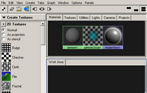
Open the hypershade , in the menubar choose window > RenderingEditors
>hypershade ). In the hypershade you'll find the components to
create materials in the create bar on your left, and two panes to
create materials. Materials are described in more detail in the material tutorial.
You can use the scale and move keys just like a 3d window
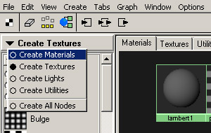
In the create bar you see different textures by default. Click on create
textures, and choose create materials. Click on a blinn
material icon, or drag ( mmb ) the icon to the lower pane (Work
Area).
N.B. With Maya 6.0 materials are located under create maya nodes > surfaces.
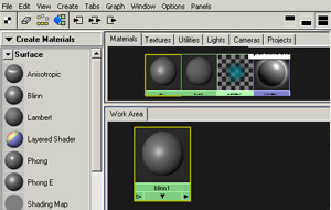
The default color is grey. To change the color, open the attribute editor
by double clicking it or using ( ctrl a )
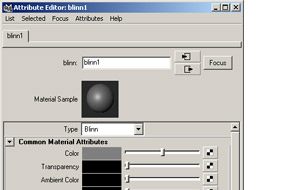
In the attribute editor you can change all settings that define the shader. We come to this later in the material tutorial, click the color chip and replace the grey color by an off white.
With the eccentricity slider you can alter the influence of the highlight, set it to create a more "glossy" material.
Change the material's name to "offwhite"

Repeat these steps to create aditional blinn shaders colored red and slightly lighter grey.
Save you're work.
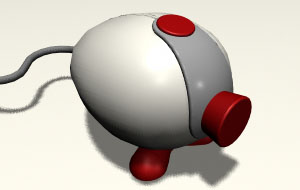
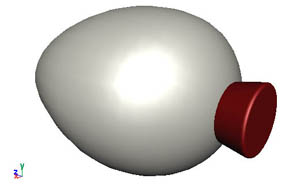
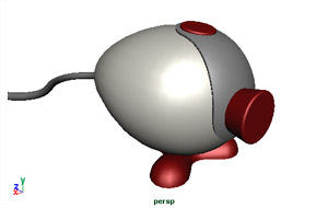
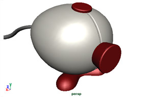
In this second section we are going to model the body of the cam out of a sphere primitive. The lens and top button are added as seperate parts in separte layers.
Start with a basic sphere ( Create > NURBS primitive > Sphere ).
Set the display smoothness to fine ( use the number keys 1,2 and 3 to change.
with the 4 and 5 key you can switch between solid and wireframe).
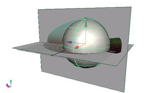
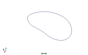
Scale and move the sphere so it roughly matches the form on the imageplane. ( use the qwerty shortcuts ).
Before we sculpt the shape we assign the white material to it, to make the
highlights visible. Select the sphere, and open the hypershade. ( window
> Rendering editors > hypershade ). Use the rmb
on the material and choose assign to selection, or drag the material
icon on the sphere.
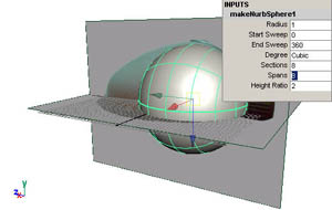
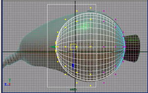
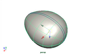
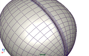
We're going to shape the sphere so we have to make sure we have enough points
to sculpt and the points are aligned to select vertical columns. Rotate the
sphere 90 degrees, and set the sections and spans to 8 in the channel
box.
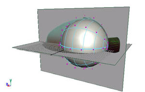
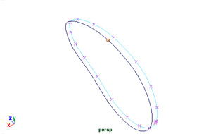
Now we will enter the interns of the sphere and edit the control vertices
by hand. On the sphere use the rmb to bring up the marking menu
that allows you to choose component selection modes. Select control vertex.
You see the cv's as purple points around the sphere. We're going to sculpt
the sphere with these points.
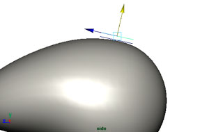
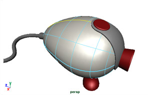
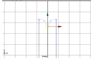
We manipulate the cv's in groups. Go to the side view and select a vertical
column, move and scale them to match the form on the image plane. Repeat this
step for the colums you see fit. The qwerty keys are particulary usefull.
w for moving, e for rotating r for
scaling. With ctrl z you can undo the last step.

The rear of the sphere could be sculpted by rotating the end cv's.
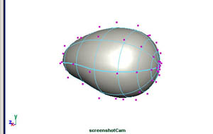
Go to the top view and do it again. It's good to see the result in 3D by rotating the camera of the perspective view.
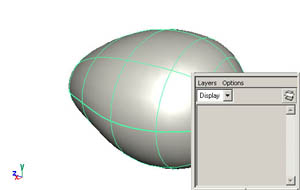
Finish the body by leaving edit mode ( To leave the component mode invoke
the marking menu again (rmb on the surface) and select "Object Mode" or "select" ) and rename the sphere
to "body". On the righthand side you see the properties of the sphere.
Change the name "Nurbs Sphere1" to "body".
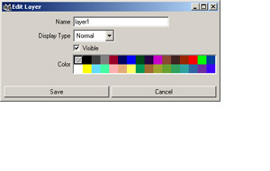
Create a new layer in the layerbar on the lower right by clicking the create
layer button. In the popup window name the layer "body_layer" and
press ok. Select the sphere and assign it to the layer by ( rmb >
add selected objects )
We create the lens out of two circels connected by a loft.
While working on the lens and button we want to disable the sphere for selection. In the layer pane you see 3 boxes, with the first you can hide / show the layer, the second controlls the mode , template or reference. Set the body_layer to template.
You can enable or disable the image planes with Panel menu > Show>
Camera's.
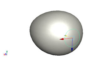
Create a circle ( Create > Nurbs primitive > Circle ). Rotate
the circle 90 degrees and move it off center, to roughly align it with the
front of the body.
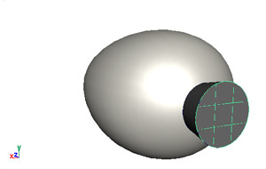
Duplicate the circle ( ctrl d ), move and scale the duplicate
to match the front of the lens. Now select both circels and create a loft
surface. ( surfaces > loft ). Add a cap to close the front,
select the front circle and choose ( surfaces > planar )
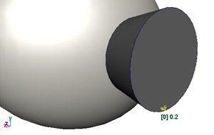
Create a small round between the side and front. ( edit NURBS >
round ). Select with a fence both the front and side surface, until
you see the yellow line and manipulator of the round. Move the yellow handles
to size the round radius.
Press return to finish the round, and the 3 key
to smooth the nurbs.
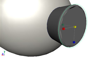
We can still change the shape of the lens by manipulating the circles. Pick a circle move or scale it. Disable the selection mask for surfaces for easier picking the circels.
Create a new layer called "lens layer" and assign the circels and surfaces to it.
Finish the lens by applying the red material. In the layer pane, right click
the lens layer and pick select all in layer. In the hypershade
right click the red blinn and pick assign material to selection.
Like the lens we build the button out of two circles. The button is slightly rotated round the body.
Create a circle ( Create > Nurbs > Circle ). Move, rotate
and scale the circle up to match the top of the body.
Duplicate the circle ( ctrl-d ) and move relative above to create
the top of the button. Double click the move icon, in the pop up window that
appears, set the mode to "object". In object mode the circle
is moved relative to it's local coordinate system.
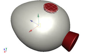
Like the lens create a loft, a planar and a round. Put it in a new layer called "button layer", and assign the red material.
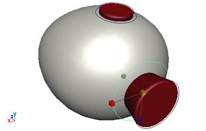
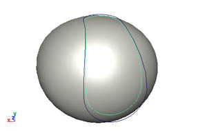
The most difficult part of this tutorial is the grey surface at the front which
connects the lens to the button.
Of course there are several methods to do it, here we present one. In the first
part we prepare the outlines of the surface. We create two half circles around
the lens and the button, and connect them with to ep curves aligned roughly
over the main body. Secondly we project this curve on a copy of the main body
and trim the unused part off.
Start by turning of the image planes: Panel menu > show > Cameras.
Duplicate both the base-circles of the lens and button and scale them up.
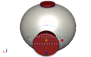
Select the circle and cut it in two. ( RMB > edit points
) select the two cutting points and choose ( Edit curves > Detach Curves
) and delete the unused part.
Create a similair half circle around the button.
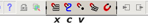
The snapping tools let you snap to grids, curves and points. The snapping
icons are located in the status line (top). The snapping tools can be accessed
by the keyboard shortcuts x ( grid ), c ( curve
) and v ( vertex ).
We connect the two curves with an edit point (ep) curve to draw points on the curve itself rather than it's control points. We snap the points to the start and endpoints of the circles.
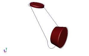
Select create > ep curve tool. Press and hold the
c key to enter the line snap mode. Press and hold the
lmb on the half circle and you can drag the point on the curve;
drag the new point to one end . Repeat this step for the end point on the
other curve and press return to finish the curve. Create a second connection
curve.
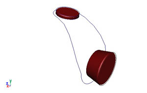
We have to align the connection lines them with
the half circles. Select one half circle and then the line, and choose Edit
Curves > align Curves with options. You want to align the line to
the half circle so set the Modify tangent on Second. You can repeat three times so you end
up with the curve ( use the g key to repeat the last action ).
Now you have to connect the four curves to one continuous curve. The attach creates a copy by default, this is not neccesairy here. Select two curves
and choose Edit Curves > Attach Curves with options. Turn
off "keep orginals" and select "connect". Repeat these steps to create a continuous
line.
Sometimes you have to reverse a curve's direction because Maya connects heads
to tails choose curves > reverse curve direction.
The grey surface lies on the sphere body and it follows the curvature. We
will create the grey surface out of the body, where we use the new created
curve as a cutting line. The resulting surface will be scaled to match the
grey surface.
For easily selecting and hiding parts, add a layer called "grey_layer" and put all the lines in it. Duplicate the sphere body and put it also in the grey layer. Hide the sphere body layer.
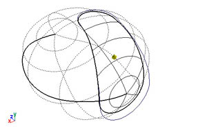
We project the curve on the duplicated sphere; select the sphere and the
curve, choose Edit NURBS > Project curve on surface with options.
In the options window select surface normal as projection method. Pick
ok to create a curve on the sphere body.
Remove the unused part with a trim. Select the sphere body and choose Edit
NURBS > trim tool . Click on the surface you want to keep and press the
return key. We duplicate ( ctr d ) the trimmed
surface and scale it to make it sleightly larger. Now you have a bottom and
a top grey surface.
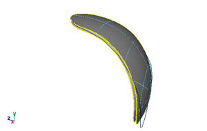
Create a loft between the bottom and top surface. Because it is trimmed the
edge curves are trim edges not isoparms. Select a trimedge ( rmb >
trimedge ) on the top and the corresponding one on the bottom surface.
( on the lower surface rmb > trimedge. with shift select the
edge )
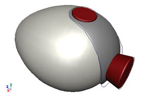
With a round you can enhance the look; but you won't easily manipulate the form anymore. Assign the grey material all surfaces in the layer.
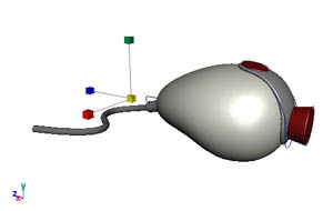
In this section we create the cable and the joint to the sphere body. We start with the joint made out of a revolve, the cable itself a simple extrude.
The joint is rotation symmetrical, and we create it by a rotating a profile round a curve.
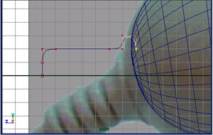
Start drawing a cv curve round the x axis, creating the basic profile of the joint.
With the curve editing tool you can modify the curvature , and normal vector
of the curve. It's very usefull when you want to align a curve to an axis,
like we want to do on the end point. Choose Edit Curves > Curve Editing
tool and select the profile curve. Make sure the end point on the axis
has a vertical tangent.
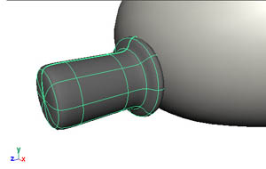
Select the curve and choose Surfaces > Revolve. You might have
to change the rotation axis.
Move rotate the joint to align it to the sphere body.
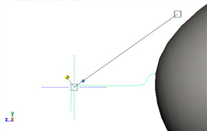
Draw the path of the cable with a cv curve starting straight
at the joint bending away.
Create a primitive circle for the profile. Scale it to fit the joint.
Select first the profile then the path. Choose surfaces
> extrude with options. Check tube, At path, Component
and Profile Normal.
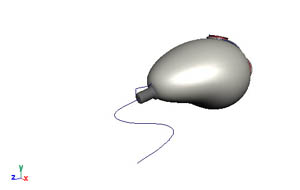
Create a layer called "cable_layer", and add the cable objects.
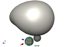
The foot is a symmetrical object, consisting of a center semi sphere, surrounded by three half spheres connected by a smooth integration surface.
Insert a new layer called "foot". Set the other layers to template, or make them invisible.
Create a sphere for the center of the foot. Scale and move it so it will
fit under the main-body. Snap it to a nearby grid point (press X
while dragging). This point will be the center of rotation, you can snap other
rotation points easily to the grid now.
Rename it to "center".
Create a second sphere and move it to the center sphere and then move it off center, in one axis. Name this sphere "outer".
Snap the pivot point to the center of the center sphere,use the insert
key to enter and leave pivot mode.
Now we cut the unused bottoms off the sphere with a detach surface. Select
the middle iso-parm ( right click > isoparm ) and choose Edit NURBS
> detach surfaces and delete the lower parts.
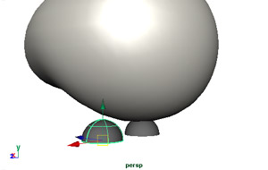
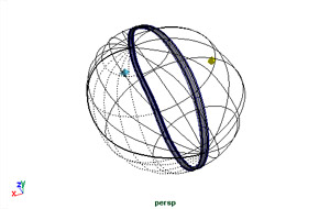
We will now create two fillet surfaces which connect the center and one of outer spheres. The fillets are created with the isoparms of the spheres, maintaining the curvature.
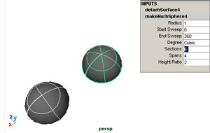
The center sphere should have a subdivision which is a multiple of three, so we can select two isoparms with an angle of 120 degrees. Select the center sphere, click on the INPUTS makeNurbSphere property and set the sections to 6 ( or a multiple of three ). You might have to rotate the center sphere to align the isoparms to the axis of the arm.
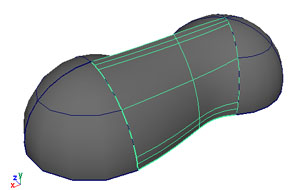
Select one isoparm of the center and one of the outer sphere. Create two
fillet surfaces ( Edit NURBS > Surface fillet > freeform fillet
) one for each site.
Because of the history we can change the scale of the sphere, and the fillet will be still aligned to the isoparm.
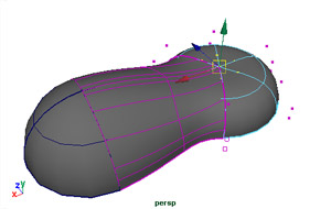
Scale both spheres and move the outer sphere of center as you see fit proportional to the body. Edit the control vertices of the center sphere and lower the middle CV's to create a socket for the body.
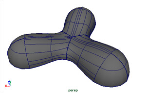
We duplicate the outersphere and the fillet twice, and rotate them 120 and
240 degrees. Select the outer sphere and two fillets. Choose edit > duplicate
and set the rotate y of the duplicate to 120 degrees. repeat this for the second arm.( now 240 degrees :-) )
Assign the red material to the surfaces. If you attach the surfaces you get rid of the hard transition.
Now you are satisfied with the shape, delete the history ( edit
> delete by type > history ) and delete two of the three arms.
It's faster to attach one arm and then duplicate them again.
First we attach the two blend surfaces together. Select them both and choose
surfaces > attach with options. Select blend instead of connect,
to smooth the surface. Then attach this surface to the half sphere. You notice
the
attach the fillets to the sheres
select the created surface and rotate copy it like before. If you want to add details you might skip this step.
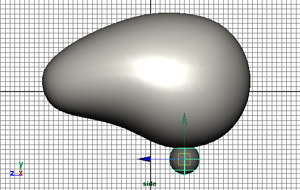
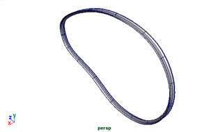
We finish the webcam by separating the body in to two half shells. This is an essential part of the plastic form. There are again a lot of methods, but we want to show you a generic method with the birail.
Copy the upper and lower isoparm ( Edit Curves > duplicate Surface
curve ). Attach the two curves, you might have to reverse one ( Edit
Curves > Reverse Curve direction ).
Duplicate the curve and move them both off centre, these will be the rails of your splitline
Now we create a profile curve that will be "lofted" round the rails. Select ep curve and snap it to the top edit points of the curves.
Now in the front view we edit the curve to create the splitline
Rebuild the curve to get more points ( Edit Curves > Rebuild curve
[] ) Choose 4 spans. And move, scale the edit points as you
see fit.
Deselect everything, and pick the edit NURBS > birail > birail 1.
With the birail to you select the profile(s) first, then the rails.
Now we trim the split-line and body surface so they match. Select
both the splitline surface and the body. And choose ( Edit
Nurbs > intersect surfaces ). This will create intersection curves
on both surfaces.
Now trim the unused surfaces of. Assign the white material to it.
The end.