Apple iMac Tutorial : 3 Textures
introduction
This tutorial is intended for industrial design students at
the TuDelft.
Version 1.1 Maya version 6
comments to d.p.saakes@io.tudelft.nl
© Aernout Peeters , Daniel Saakes, TUDelft 2003,2004
All rights reserved.
In the next steps, you will learn about:
- texturemaps for bumpmapping
- texturemaps for transparency
- a layered shader for combinig different materials
- 2D-placements for texturemapping
- 3D-placements for texturemapping
- 3D-projections for texturemapping
If you start here: open the start_textures.mb file in the tutorial project.
color mapping
Start by duplicating the "white_plastic"-material.
In the hypershader choose edit > duplicate > shading network. Apply it to the base surface. Open the attributes of the duplicated "white_plastic"-material. Rename it to "base_plastic".
Middle mouse drag the base_plastic node to the Work Area Use the input and output connections button  to center the node.
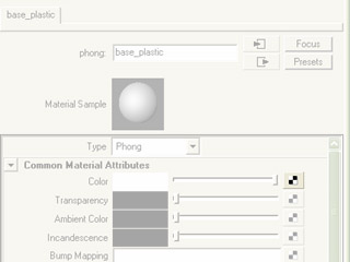
Open the attributes of the base_plastic material to replace the color chip with a texture map. Click on the checker  right from the color slider.
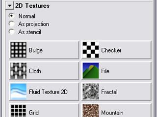
In the Create Render Node window that opens you can choose various types of texture maps. In this case we will use a file texture, so click on the File to map an image.
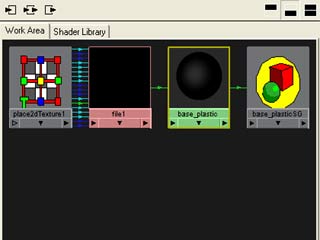
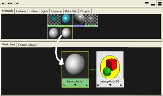
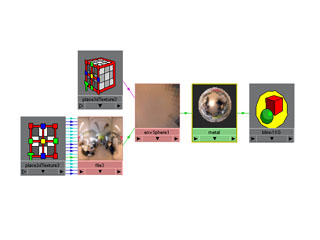
In the hypershader again zoom out with the default camera controls. In order to organize the nodes again: select the base_plastic node with the lmb ( the green one probably on the right. It's border should become yellow. Then press the input and output connections .
From left to right you see a place2dTexture node with a lot of connections to the file node. De file node is connected to the base_plastic phong node. Sometimes you will see a shading group node if the material is used in the scene.
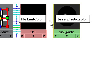
If you hover over the connecting line you will see that the outcolor of the file is mapped to the color attribute of the phong called "base_plastic".
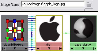
The "base plasic" and file node are both black because there is no image yet. Click on the file node and in the attribute editor click the file icon next to the Image Name and locate apple_logo.jpg in the source images folder.
Assign the base_plastic to the base of the iMac by mmb drag the base_plastic on it, if you didn't do it already.
In order to see the texture , enable Panel Menu » Shading » Hardware texturing. To improve the quality of the texture select the base_phong" material and in the hardware texturing tab set the texture resolution to highest.
The logo is drawn completely over the surface and we now shrink it and map it on the front with the 2d texture placement node.
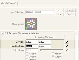
Graph the base_plastic-node in the hypershader and open the attributes of place2dTexture node . We will use the Coverage and Translate Frame to place the logo on the surface. Change Coverage to 0.5 ,0.5. Notice that the texture fills roughly a quarter of the base. The texture is rotated. With the Rotate Frame you can rotate it 90 degrees.
In the attributes editor of the placement node select Interactive Placement.
Around the logo appears a red frame, with 9 handles: the centre is for moving, the corners are for rotating and the handels on the sides are for scaling. You have to use the middle mouse button.
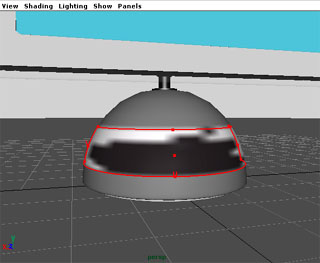
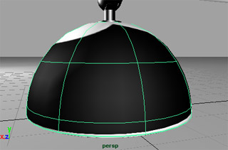
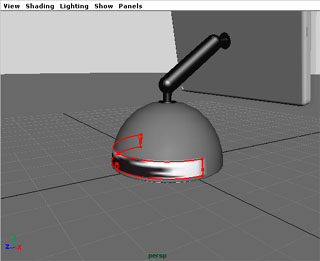
Middle Mouse Button drag the centre handle to position the logo to the front of the base and scale it so it matches the next picture. You will notice that the mapping follows the topology of the NURBS surface, so it shrinks if you move to the top.
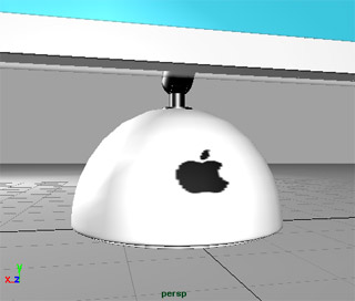
The color around the texture is defaulted to grey again. To turn it white, open the attributes the File Node in the hypershadepanel. In the Color Balance tab set the Default Color to white.
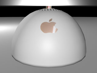
Now you will have a black apple logo on your Imac. In a few steps from now you will create a the metal ( more convincing ) version of the logo.
bumpmapping

By adding a grainy bumpmap to a material you can achieve very realistic matte effect. Bumpmaps alter the way light reflects on a surface and can be mapped independently from the color channel. So will add some graininess to the base plastic material.
Bumpmap show up only in a rendering so will use the IPR again to tune the effect.
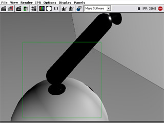
First setup the ipr renderer. In the renderpanel IPR » IPR Render » detailCam and select the base for tuning.

Open the attributes of the "base_plastic"-material. Now map the bumpmap just like the color. Hit the checker behind Bump Mapping .
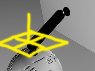
In the create window choose from 3D Textures » Rock. Organize the network ( select the base plastic node and press the button ). so it matches the picture.
The network consists of two mappings now. The apple logo mapped on the color and the rock texture mapped on the bumpmap attribute of the basePlastic phong node. Since the rock is a 3D texture, it has a place3dTexture node instead of the 2d for the apple logo.
In a bumpmap the value of the color is used as a height difference. In the bump 3D node you can control the amount of height differences and the size of the grains can be manipulated in the 3D placement node.
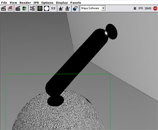
The result in the ipr is much to grainy, so graph the "base_plastic"-material again, open the attributes for "bump3d" node and reduce the Bump Depth until it becomes only slightly visible in the renderpanel ( to zero )
The rock is a so called 3D Texture; which is not mapped on the surface but has a (color) value for every point in space. The advantage is that you don't have to worry about NURBS surface topology.
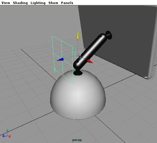
The bumps are a bit too coarse still, so you will have to scale the texture down. Select "place3dTexture#" in the hypershadepanel. Go to wireframe mode and you will see a green cube that shows the scale and position of the rock texture.

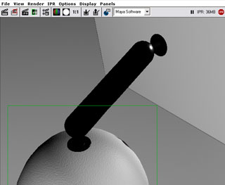
Using the scale tool in the toolbox, uniformly scale the texture down until it becomes fine in the ipr render view.
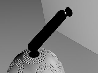
If you're still not satisfied, reduce the Bump Depth some more until it reaches almost "0".
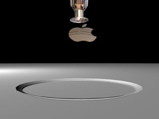
projection mapping
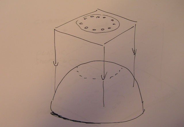
On the top of the base is around the hinge a circular array of holes is located. This can be simulated using textures in two ways; displacement mapping and bumpmapping. For now bumpmapping suffices. You probably have noticed that the top of the sphere shrinks the textures when directly mapped like the apple logo. So we will use a projection mapping.
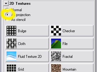
Duplicate the original "white_plastic"-material again, open it's attributes and rename it to "base_holes". Apply the new material to the base and Bump Mapping » 2D Textures.Now pick the As projection radio button. then choose File
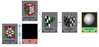
Organize the network. Now you will see at the left bottom the file texture with a 2d placement which is placed with a 3D texture placement in 3D through the projection node. The output of the projection node is the input for the bumpmap3D node.
Open the attribute editor of the file2 and load the holes.tif image.
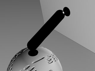
Render the detail camera. Notice the deformed holes on the base. You will have to rotate and place the projection.
The default projection is a plane which is alright for projecting the holes. Review the attributes of the projection node for the projection types.
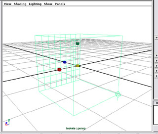
In the hypershade panel, graph the "base_holes"-material, select "place3dTexture#". In the detail camera view you can move up the projection outside of the base with the move tool.
You can see that the projection has a planar form with a pin extruding from it; the plane represents the texture being projected and the pin the direction of the projection
Since the pin is not facing downwards, rotate the texture along the x-axis by "-90" degrees, either numerically or with the rotate tool
With the texture still selected, scale the texture with the scale tool, so the inner circle of the holes fits the hinge quite tightly. You can see that the holes are put on the surface multiple times unfortunately. Open the attributes for the "place2dTexture#" in the graph of the "dome_holes"-material and uncheck both Wrap U and Wrap V.

Now you can see the edge of the texture as bump. Solve this by opening the attributes for the "File#" in the same graph as before and Color Balance » Default Color » raise it to perfect white.

Render again.
environment mapping

Since the base color of the environment is black, this is reflected in the arm as well, fortunately, this can be better. You will simulate an environment by adding a reflectionmap. In this case you will use a panorama image and project it around the scene.
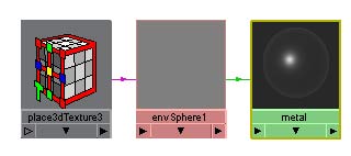
First prepare the metal material. Open the attributes of the "metal"-material, then map the Reflected Color. Choose from Environment Textures » Env Sphere
After organizing your network should look like above. A 3D placement to control the reflections position
In the envSphere node map the Image with 2D placement. Make sure you switch As Projection to Normal and choose a file texture.
We've prepared a panorama environment image of the old studiolab design. To map it: double click the file node and locate the studiolab.jpg image in your project folders.

Render the image. After rendering you should see a reflection of the old studiolab.
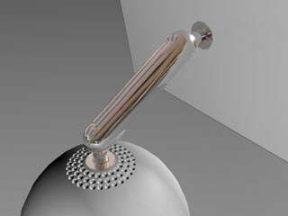
Render the scene again with raytracing on and notice the differences. Most notably, reflections of objects in objects.
Save your work and continue with the
combining multiple materials
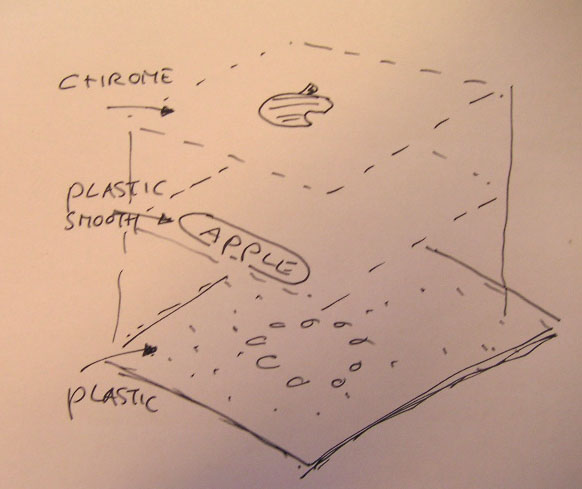
The logo actually has a chrome look. For this you will use the same material you used before for the metal parts.
The Apple logo should be on top of the existing plastic material; this is possible by using a layered shader, which is capable of combining effect of multiple materials on a single surface.
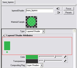
Create a Layered Shader from the creation bar and call it "base_layered". Apply it to the base: it will become green. In the attribute editor you will see a red rectangular area where you can place multiple materials, just like layers in photoshop.
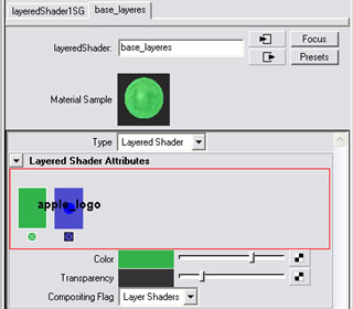
In the hypershadepanel select the "metal"-material and Edit » Duplicate » Shading Network and call it "apple_logo". Select with shift the layered shader and graph both networks.
Open the attribute editor of the layered shader again and MMB drag the new apple_logo material node in the red rectangle of the layered shader, next to the green material.
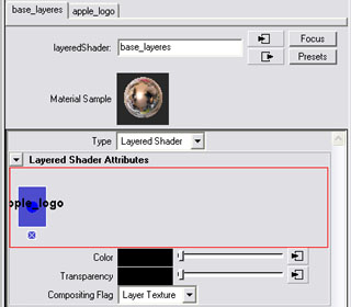
Remove the green material by clicking on the x below. And change the compositing flag to layered texture. Render the view: you will see a completely metal base. Which is actually not quite bad :-)
Now you are going to mask this metal material so it will only show the apple logo.
In the base_plastic node you've placed the black and white logo on the base. Now you are going to use this image and placement as a mask for the metal apple logo: as a transparency map. The white parts become transparent and the black parts opaque.
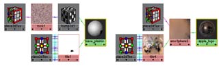
graph both the base_plastic and the apple_logo networks in the workarea.
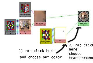
Now connect the output of "file#" node (containing the Apple logo) to the input of the "apple_logo"-material. Rmb click the output connector of the file node and choose Out Color » outColor a line will be attached to your pointer. Go to the input connector of the apple logo material and rmb click and choose Transparancy.
render the result: you will see only a metal looking apple logo.
If you see the base highly translucent shine; then you probably forgot to change compositing flag in the layered shader mode to layered texture
Now open the layered shader again. Mmb Drag the "base_holes"-material in the red rectangle; behind the metal. And render again.
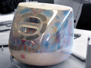
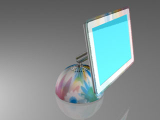
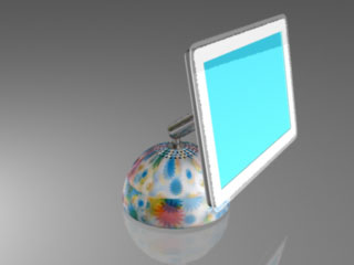
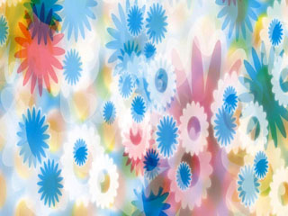
Unfortunately the iMac is looking a little pale, so let's add some color then. A few years back, Apple released a "flowerpower" version of the original iMac; we'll make a "flowerpower" version of the new iMac.
Render your scene again and notice the color on the base of the iMac. You can see the color, but it doesn't look quite right yet. First of you're using a planar projection, which isn't really suitable for curved surfaces. Second, the projection itself is too small.
In the hypershade graph the "base_ holes"-material and open the attributes of the projection-node attached to the "flowerpower"-picture. Now, change the Proj Type (projection type) from planar to cylindrical. Render it once more.
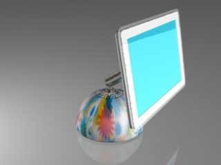
Unfortunately there's still a seam visible; the projection is still too small. Select the "place3dTexture#" attached to the projection-node and scale it up to at least twice its current size. If you render now, it should look right.
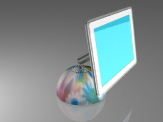
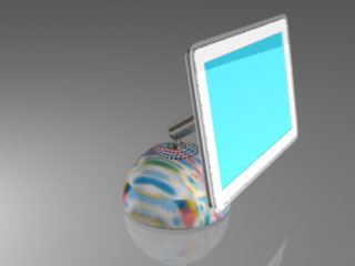
There's another projection method you'll try now. In the attributes of the projection-node (attached to the Flower Power picture), change the Proj Type from cylindrical to spherical and render the scene to spot the differences.
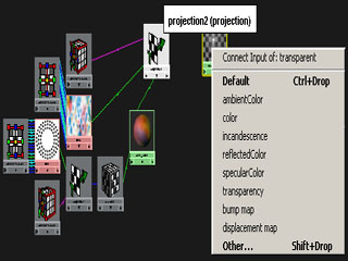
If you'd like, you might add some color to the transparent rim as well, creating a colored transparent plastic. Select both the "base_holes" -material and the "transparent" -material and graph them. MMB-drag the projection -node (attached to the "flowerpower" -picture) to the "transparent" -material. When you see a menu appearing, select color.
 >> choose As projection >> File >> Image